Click or tap image to expand
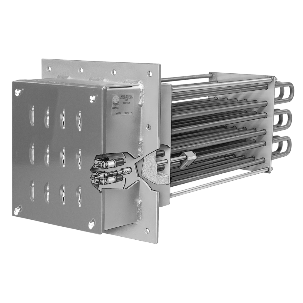
Duct Heaters: Standard and Finned Tubular
Why Choose Tempco for Duct Heating Solutions?
At Tempco, we manufacture rugged, high-performance duct heaters engineered to meet the demands of industrial environments.
Whether you’re heating clean air in a manufacturing facility or handling high-volume process airflow, Tempco’s duct heaters deliver reliable, long-lasting performance. Our designs feature heavy-duty, field-replaceable Incoloy® tubular elements, durable housings, and a variety of mounting and control options — all built to withstand vibration, corrosion, and harsh conditions.
We offer both standard and custom models, supporting fast lead times and tailored specifications to meet your project requirements. From OEMs to maintenance teams, engineers across industries trust Tempco for efficient, safe, and dependable air heating solutions.

Typical Applications:
- Air Drying/Curing Operations
- Annealing
- Autoclaves
- Booster Air Heater
- Breaking Resistor
- Core Drying
- Dehumidification
- Forced Air Comfort Heating
- Heat Treating
- Make-Up Air Heating
- Re-Heating
- Resistor Load Banks
Design features
Standard Tubular Duct Heaters
- NEMA 1 General Purpose Ventilated Enclosure
- Painted Steel Mounting Flange
- Single- and Three-Phase Wiring
- 3-1/2″ (89 mm) Insulation
- Field Replaceable Incoloy® 840 Elements
- Element Bends Re-pressed
- 1/4″ (6 mm) Inside Diameter Thermowell
- Stainless Steel Support Plate and Corner Posts
Finned Tubular Duct Heaters
- NEMA 1 General Purpose Ventilated Enclosure
- Stainless Steel Mounting Flange and Terminal Box
- Single- and Three-Phase Wiring
- 1″ (25 mm) Insulation
- Field Replaceable .430 Diameter Stainless Steel Elements
- 9/32″ (7 mm) ID Sensor Thermowell
- Stainless Steel Support Plate and Corner Posts
- Stainless Steel Insulation Housing
A – Enclosures
NEMA 1 terminal box enclosure with vented cover to help keep wiring cooler. Optional enclosures: NEMA 4 (moisture resistant), NEMA 7 (explosion resistant) and NEMA 12 (dust resistant).
B – Insulation
3-1/2 inches (89 mm) of mineral insulation in a stainless steel enclosure below the mounting flange, minimizes heat losses while keeping the electical wiring cooler.
C – Frame
The heavy duty frame is composed of a 1/4 inch (6 mm) thick steel mounting flange, stainless steel support plate and corner posts to securely hold the heating elements rigid in any mounting position.
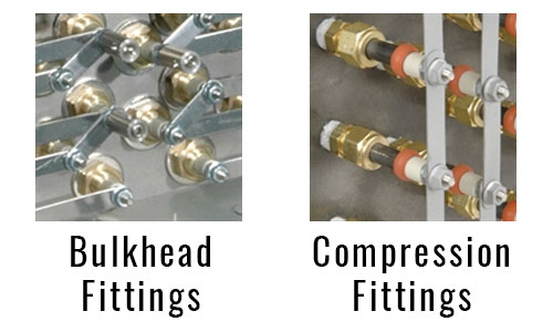
D – Field Replaceable Elements
Standard field replaceable elements are held in place with single-screw quick-release “V” clamps. Pressure resistant designs utilizing welded elements, bulkhead fittings, or compression fittings to attach elements to the flange are available to limit leakage of ducted air or gases into the terminal enclosure. Welded elements are used for gas tight applications.
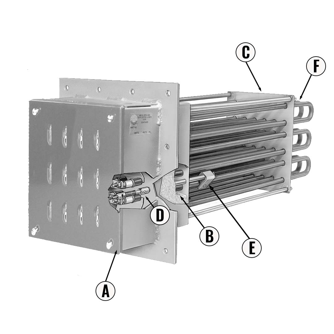
E – Thermowell
A 9/32″ (7 mm) inside diameter thermowell accessed through a 1/8″ NPT tapped hole in the flange allows installation of an optional Type J or K thermocouple for sensing temperature within the element bundle. It can be clamped directly to an element for use as a high limit providing a faster response. An excellent safeguard for your system.
F – Incoloy® Elements
The .430″ (11 mm) diameter elements are silicone resin sealed. High temperature tubular duct heaters utilize Incoloy® sheath material for excellent high temperature scaling and corrosion resistance. The medium temperature finned duct heaters have stainless steel fins on a corrosion resistant stainless steel sheath. High temperature Incoloy® elements have all bends repressed in special dies to recompact the MgO refractory to eliminate any electrical insulation voids and hot spots.
Sizing a Duct Heater
To properly match a duct heater to an application, the wattage, air velocity and element watt density must be determined.
Formulas and graphs that will aid in your design include:
- Wattage calculation formulas and table
- Element Watt Density vs. Sheath Temperature and Air Velocity Graph
- Pressure Drop vs. Air Velocity Graph
In most applications the following design limitations should be adhered to:
- Maximum watt density of 40 watts/in2 (6.2 watts/cm2 )
- Maximum element sheath temperature of 1400°F (760°C)
- Minimum air velocity of 200 feet per minute (61 meters per minute)
- Maximum voltage for UL certified heaters is 480V.
- Maximum voltage for CSA certified heaters is 600V.
Calculations
Minimum Wattage Requirement
This table is for quick-estimation purposes and is based on air under standard conditions (70°F inlet air temperature at 14.7 PSIA).
If flow is given in CFM at operating temperature and pressure it can be converted to SCFM (Standard Cubic Feet per Minute) with the following formula (use the equations to the right for compressed air):
P = operating pressure (gauge pressure + 14.7)
T = operating temperature

Note: Remember when calculating wattage to use the maximum anticipated air flow and to compensate for any heat losses.
For free air use equations:
For compressed air use equations:
| Amt. of Air CFM | Temperature Rise (°F) | ||||||||||
|---|---|---|---|---|---|---|---|---|---|---|---|
| 50 | 100 | 150 | 200 | 250 | 300 | 350 | 400 | 450 | 500 | 600 | |
| Kilowatt Hours to Heat Air | |||||||||||
| 100 | 1.7 | 3.3 | 5 | 6.7 | 8.3 | 10 | 11.7 | 13.3 | 15 | 16.7 | 20 |
| 200 | 3.3 | 6.7 | 10 | 13.3 | 16.7 | 20 | 23.3 | 26.7 | 30 | 33.3 | 40 |
| 300 | 5.0 | 10 | 15 | 20 | 25.0 | 30 | 35.0 | 40.0 | 45 | 50.0 | 60 |
| 400 | 6.7 | 13.3 | 20 | 26.7 | 33.3 | 40 | 46.7 | 53.3 | 60 | 66.7 | 80 |
| 500 | 8.3 | 16.7 | 25 | 33.3 | 41.7 | 50 | 58.3 | 66.7 | 75 | 83.3 | 100 |
| 600 | 10 | 20 | 30 | 40 | 50.0 | 60 | 70.0 | 80.0 | 90 | 100 | 120 |
| 700 | 11.7 | 23.3 | 35 | 46.7 | 58.3 | 70 | 81.7 | 93.3 | 105 | 116.7 | 140 |
| 800 | 13.3 | 26.7 | 40 | 53.3 | 66.7 | 80 | 93.3 | 106.7 | 120 | 133.3 | 160 |
| 900 | 15 | 30 | 45 | 60 | 75.0 | 90 | 105 | 120 | 135 | 150 | 180 |
| 1000 | 16.7 | 33.3 | 50 | 66.7 | 83.3 | 100 | 116.7 | 133.3 | 150 | 166.7 | 200 |
| 1100 | 18.3 | 36.7 | 55 | 73.3 | 91.7 | 110 | 128.3 | 146.7 | 165 | 183.3 | 220 |
| 1200 | 20 | 40 | 60 | 80 | 100 | 120 | 140 | 160 | 180 | 200 | 240 |
Note: For additional information or help with your application please contact TEMPCO.
KWH TO HEAT AIR AT SELECTED FLOW RATES
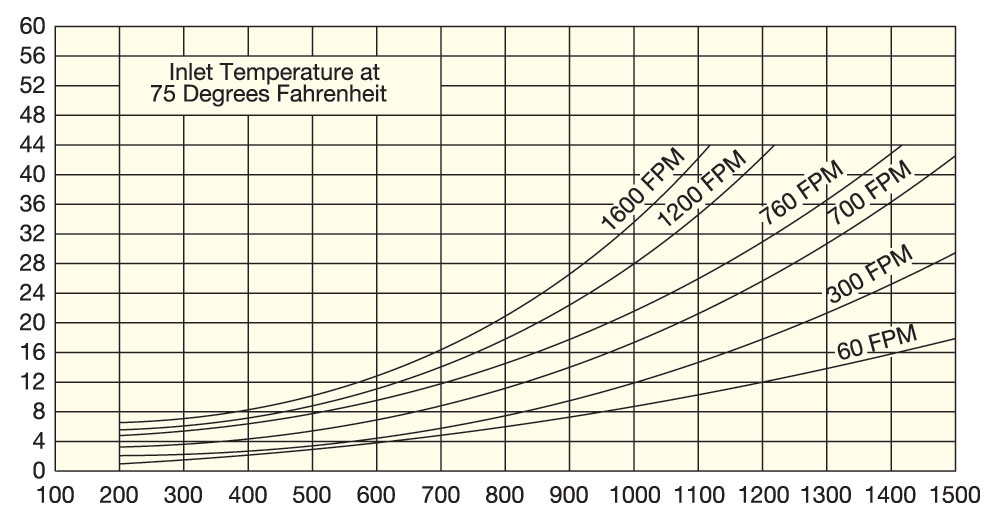
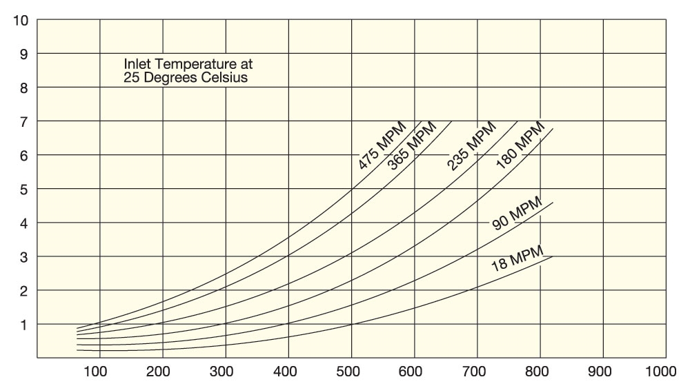
Element Watt Density vs. Air Temperature and Air Velocity
Use graph (English or Metric) to plot Outlet Air Temperature vs. Outlet Air Velocity to determine Element Watt Density.
The recommended watt density is based on a maximum element sheath temperature of 1400°F (760°C). Air and other gases that are poor conductors of heat require watt densities matched to the velocity of the gas flow to prevent element overheating. Selecting a lower watt density for the heating elements will extend heater life expectancy.
Element Watt Density is the wattage dissipated per square inch of the element sheath surface and is calculated with the following formula.

Air Velocity (feet per minute)
English
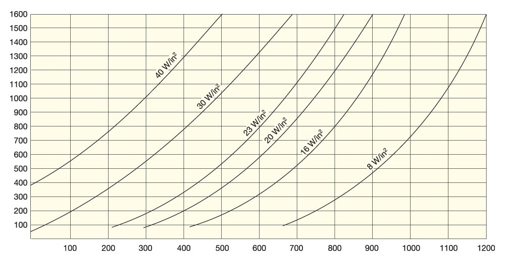
Process Temperature °F – Approximate Sheath Temperature 1400°F
Air Velocity (meters per minute)
Metric
Process Temperature °C – Approximate Sheath Temperature 760°C
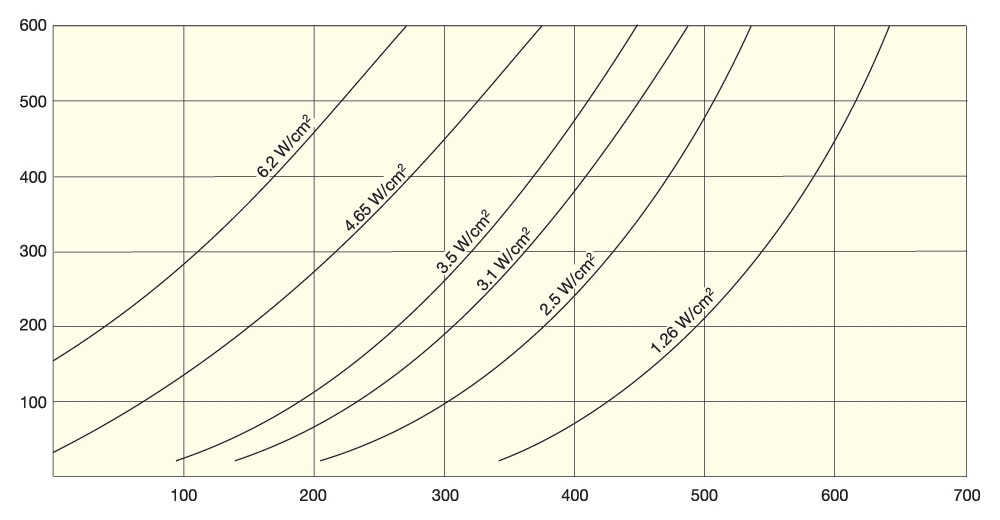
Element Watt Density vs. Sheath Temperature and Air Velocity
Use graph (English or Metric) to plot Watt Density vs. Air Velocity to determine Sheath Temperature.
Use graph (English or Metric) to plot Watt Density vs. Sheath Temperature to determine the required Air Velocity.
Watt Density (W/in2)
English
Sheath Temperature (°F)
Watt Density (W/cm2)
Metric
Sheath Temperature (°C)
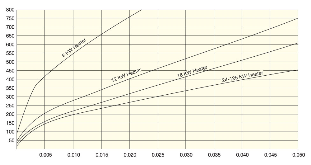
Pressure Drop vs. Air Velocity
Use graph (English or Metric) to plot Pressure Drop vs. Air Velocity for standard duct heater sizes used to properly Size Blowers.

Air Velocity (feet per minute)
English
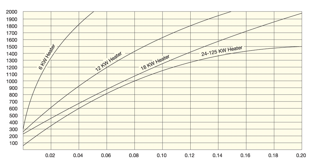
Approximate Pressure Drop (inches of water)
Air Velocity (meters per minute)
Metric
Approximate Pressure Drop (Kilopascals)